Final Drive Box – All 850/1000 Models
Stripping and Reassembly Procedure
Stripping and Reassembly Procedure
The Moto Guzzi rear bevel drive box may need overhauling to cure oil leaks or replace worn parts. Instructions for dealing with this item are sparse in the usual literature – 'dismantling of the bevel drive is beyond the scope of this book', etc. is a common example.
Faults
- Wear or damage may be indicated by a high-pitched whine
- Excessive backlash between crown wheel and pinion may be assessed by holding the output shaft ('hollow spindle') tightly and rotating the input shaft in both directions
- Lateral play in the crown wheel/output shaft may be felt by pulling and pushing the shaft
Oil Leaks
- Oil on wheel and tyre:
- Inner (large) oil seal failed
- As above plus inside of hollow output shaft oily:
- Outer (small) oil seal failed
- Oil from casing:
- Gasket(s) failed
Casing porous - Oil from swing arm joint:
- pinion O-ring(s) failed
The 'inner' (large) oil seal ('inner/outer' refers to position of seal relative to wheel hub, not accessibility in drive box!) is easy to change, being inserted from the outside of the casing cover. If, however, the 'outer' (small) oil seal or gaskets or O-rings need replacing the only recourse is to rebuild the drive box, also if main casing is damaged or is to be replaced or needs work on it such as repairing damaged threads, etc. Both seals will have suffered damage if there has been swarf or grit in the oil, so if doing one repair it is often wisest to renew all seals and gaskets regardless of their apparent condition in any event.
The component parts of the bevel drive box are shown in Figure 1.

Figure 1: drive box component parts
Parts key to Figure 1
- Level plug and washer
- Filler plug and washer
- Drain plug and washer
- Swing arm to drive box O-ring seal
- Pinion and housing
- Pinion housing to casing O-ring seal
- Cover bolts, 8 off
- Cover
- Main casing
- Output shaft ('hollow spindle') ball bearing
- 'Inner' (large) oil seal
- Cover gaskets
- Crown wheel distancing shim(s)
- Crown wheel with output shaft ('hollow spindle') and roller bearing inner race
- 'Hollow spacer' (sleeves wheel spindle)
- 'Outer' (small) oil seal
- Roller bearing outer race and rollers' retainer ring
- Caged rollers (not shown)
Dismantling The Bevel Drive Box – Procedure
After removing the rear wheel, detach the suspension unit lower lug from its stud on the drive box casing. Undo and remove the four nuts with lock washers connecting the drive box to the swing arm, and withdraw it complete with drive shaft and coupling sleeve. Before opening, clean exterior with petrol or paraffin to remove all traces of grease and dirt.
Proceed as follows:
- As an aid to all further stages, unscrew and remove suspension mounting stud from the main casing I.
- Knock down the locking tabs of bolts G, and unscrew and remove all bolts.
- Remove cover H with gaskets L and shim(s) M. If gaskets stuck, gently rotate cover by tapping sideways with a soft drift to break them (do not lever off with brute force!). Discard all gaskets.
- If not captive in bearing J, withdraw crown wheel and 'hollow spindle' N from casing I.
- From the roller bearing outer race, withdraw the caged rollers R. Mark with indelible pen to identify which way up it was.
- Withdraw pinion housing E. If made difficult by studs fouling, carefully loosen or unscrew the studs with molegrips (do not damage threads!).
- From housing E, remove and discard both O-rings D and F.
- From outside face of main casing I, tap out the hollow spacer O using a round drift only slightly smaller than wheel spindle hole in casing.
- Important – make a note how far end of roller bearing outer race Q protrudes from its recess, if any.
- From casing I withdraw the outer race Q* with retainer ring to gain access to outer (small) oil seal P, if it is to be renewed.
*IMPORTANT: Please Note that removing outer race 'Q' is usually beyond the ability of the home mechanic without a special puller. In this case you are recommended to entrust this task to a specialist engineering shop for a modest fee; a typical technique involves expanding the casing in an oven to loosen the race (and this is not quite the same type of oven as found in your kitchen!)
- Remove and discard oil seal P.
- Remove and discard oil seal K.
Inspections
Ensure that:
- there are no cracks or leaks in casing or cover.
- roller bearing recess is not damaged or scored.
- all gasket faces are not scored or damaged and are smooth.
- all threads in casing are in good condition.
- If not have repaired or replace with e.g. good second hand – bad drain threads always cause trouble sooner or later!
- cover's ball bearing and seal recesses are not damaged or scored.
- shims are perfectly flat and not scored or nicked.
- surface of hollow output spindle where fits in ball bearing J is good, plus surface contacted by inner (large) seal K, plus splines.
- bevel gears are not chipped or excessively worn.
- roller bearing parts not excessively worn.
- If so, the entire set must be replaced including retainer ring, and:
- Requires 2-legged puller to draw old inner race from hollow spindle.
- working face of roller retainer ring not excessively worn.
- ball bearing not excessively worn.
- pinion and its tapered rollers not sloppy in their housing.
- If so the assembly must be rebuilt with new parts as necessary, which:
- requires spanner and holdfast capable of undoing nut on input shaft (Figure 5).
- internal splines of drive shaft coupling sleeve not excessively worn. If so, replace it.
- circlips (3 off) on pinion shaft and drive shaft not loose. If so replace them.
Bevel Drive Box Reassembly – Procedure
Proceed as follows:
- Introduce a new outer (small) oil seal P into its recess in casing I.
- DO NOT attempt to press or drift it fully home into its recess at this stage!
- Place roller retainer ring into its recess, on top of oil seal P. (If showing some wear, reinsert it back to front, good side uppermost.)
- Introduce roller bearing outer race Q into its recess.
- Double-check retainer ring and seal are in first!
- Using a 3-legged universal puller adapted as shown in Figure 2, begin to carefully press outer race into its recess by tightening puller bolt. Ensure race is straight at all times.
- IMPORTANT: DO NOT press it fully home into its recess at this stage!
- Continue turning until depth of race is approaching its previous position as noted during disassembly, step 9, above.
- Note also that towards the end of its travel the oil seal is also being pressed into its own recess such that the retainer ring is held between the two.
Figure 2: method for pressing roller race into casing
- Remove all puller components.
- Temporarily replace caged rollers R into outer race Q, same way up as noted in step 5 during disassembly; followed by crown wheel assembly N, shim(s) M (important!) and cover H. Note: be extra careful not to damage oil seal P during this procedure.
- Press down on cover (initially) and temporarily replace 2 bolts G (latterly), diametrically opposed, and tightened lightly.
- With thumb or finger through pinion orifice, attempt to rotate crown wheel.
- If crown wheel revolves freely, go directly to step 14.
- If crown wheel stiff or unable to move remove cover, crown wheel and caged rollers.
- Re-apply puller as per Figure 2 and further press outer race by the equivalent of one half turn only of the bolt (which does not include the initial turns necessary to tighten the puller before the race begins to move!).
- Go to step 6 above.
- If here, remove cover, crown wheel and caged rollers.
- By adopting the same technique, again use the puller to press hollow spacer O fully into wheel spindle hole in casing I , see Figure 3.
Figure 3: pressing hollow spacer into casing
- Install a new inner (large) oil seal in cover.
- As a guide as to the condition of this seal, its inner diameter must be slightly smaller than that of the bearing and some small friction by it gripping the output shaft should be felt following step 17 below.
- If hollow spindle N is not a reasonably tight fit in bearing J, neatly apply a film of locking compound to contact surface with bearing and install fully; crown wheel is now 'attached' to cover. This must then be left for several hours for the compound to set before continuing.
- Fit a new O-ring F onto pinion housing E.
- Insert the pinion housing into its orifice in main casing I.
- IMPORTANT: MAKE SURE the two flats with oil holes on the housing body are aligned with the two cutouts in the bottom of the casing orifice (hint: the outside [furthest away from wheel] edge of the square fixing flange is curved to match shape of casing and not straight like the remainder).
- If loosened during disassembly, retighten fixing studs.
- Temporarily clamp down housing E into its normal working position in casing I by a pair of the fixing nuts with two lock washers beneath each as spacers (stud threads do not go all the way down); this is required to compress the O-ring F.
- If components are being reassembled in a 'new' main casing, ensure pinion does not foul the cast bracing web immediately in front of it.
- If so, some extra 'pinion shimming' may be achieved by adding thin gaskets beneath O-ring F.
- NB such gaskets have been provided in the past as part of a full gasket set for early 850/1000 models, but do not seem to be readily available singly, and are not normally mentioned in the usual maintenance literature.
- Suitable gaskets may be made from brown paper (Figure 6).
- Replace caged rollers R into outer race Q, again same way up as noted in step 5 during disassembly.
- On casing joint face place a new gasket L, shim(s) M followed by second new gasket.
- Reinsert crown wheel assembly N with cover H, ensuring that gears mesh properly and taking care not to damage oil seal P.
- Replace bolts G not forgetting washers and locking tabs, and lightly tighten in an even and diametrically opposed sequence.
- Ascertain the average amount of free play between gear teeth by holding hollow spindle N, and rotating pinion forwards and backwards at different positions of crown wheel.
- Further tighten bolts G in equal small increments.
- Assuming casing I is the original (i.e. a rebuild with same components), the bolts should be fairly well tightened (but do not overtighten!) leaving a barely discernable amount of free play between the gears, as originally.
- Moto Guzzi specify this final clearance between teeth to be in the range 0.1 to 0.15mm (Figure 4).
- If, following this, gear movement becomes stiff or locks solid then there is not enough clearance, typically due to one or more vital components being renewed (e.g. main casing). This will require either:
- extra shim(s) M added (available sizes: 0.8, 0.9, 1.0, 1.1, 1.2, 1.3mm);
- alternatively, for small changes, extra gasket(s) L.
- In either event remove then replace cover H with the necessary changes to M and/or L, then go back to step 24 above.
- extra shim(s) M added (available sizes: 0.8, 0.9, 1.0, 1.1, 1.2, 1.3mm);
- If there is still a large amount of free play left (e.g., makes a plainly audible 'clonking' noise during step 26) after the bolts are fully tightened, then the cover must be removed and shims M reconfigured to reduce the clearance. After this again resume step 25.
Figure 4: Drive box – factory settings for gear teeth clearances
- If you are here, then the most difficult part of the reassembly is completed. Final measurements should be as shown in Figure 4 above. Due to uneven wear of the teeth, some backlash may still be evident in one or two places; the object is to ensure that there is some clearance at all positions of the crown wheel.
- If the gasket faces of casing and cover are not perfect, it is permissible to apply a thin smear of non-hardening gasket sealant to each prior to final asembly.
- Upon final assembly, bend up the locking ears of all bolts G.
- Apply a drop of locking compound to the thread of the suspension mounting stud and replace in outer cover.
- Remove temporary pinion housing holding nuts and washers, and refit drive box to swing arm.
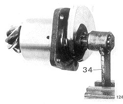 Figure 5: Dismantling pinion housing requires special techniques. The drive shaft coupling sleeve may be adapted in place of '34' to hold splined shaft with e.g. a chain wrench or gripped in a vice. Note that nut incorporates a sleeve, locked to shaft by being punched down between two of the splines |  Figure 6: pinion housing to casing gasket. Size of central hole same as diameter of housing body (O-ring sits on top) (this example is from an actual Moto Guzzi gasket set, so there!) |
Refitting To Swing Arm

Figure 7: finished drive box can't simply be bunged back onto swing arm without realignment
With reference to Figure 7 above, reattach drive box to swing arm A complete with drive shaft not omitting O-ring (Figure 1, D) and spring washers under the fixing nuts.
- Temporarily insert wheel spindle B in Figure 7 through the L/H arm of the rear fork and the drive box.
- Tighten fixing nuts C in Figure 7 with their washers in a diagonal sequence. Then withdraw wheel spindle B which should come out effortlessly.
- If it offers any resistance it is necessary to loosen nuts C and rotate the casing left or right until the spindle will slide most easily through the swing arm and drive box.
These instructions were founded on the guidelines published in factory workshop manual. Figures 1, 4 – 7 copyright © Moto Guzzi; Header pic © Haynes Publishing Group 1981/Moto Guzzi